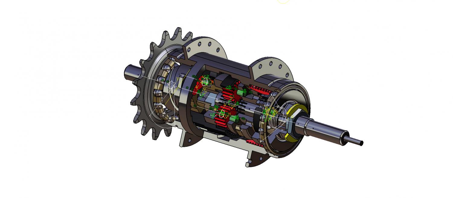
Mechanical Design/ Machine Design: Build your own machine!
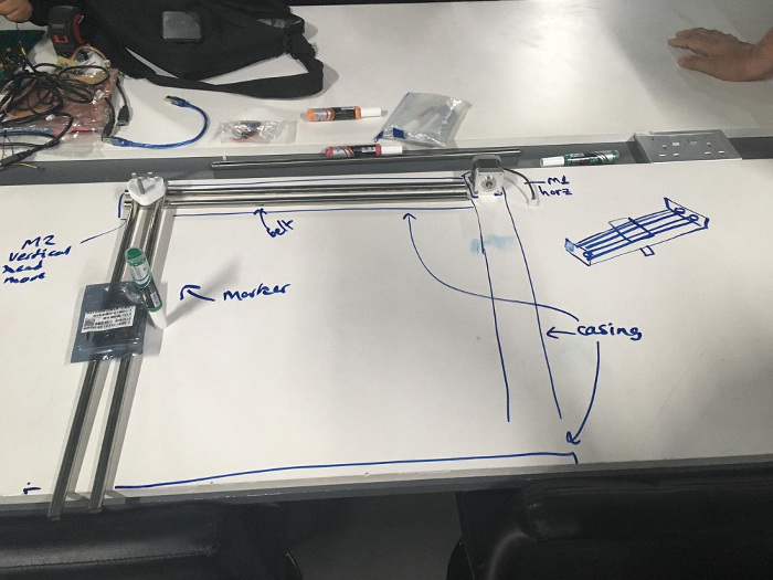
this week we needed to come up with the machine we want to make in machine design week. we suggested multiple ideas one of them is 3d clay machine but due to time restrictions to produce everything we decided to go with something simpler. we suggested to work on 2d machine and thought about different applications. we settled on a plotter with a uniqe head that llow us to attche different things on it in future, but for now we are going to attach a pen to it.
Team plans
For machine design week, QBIC Fab Lab students decided to design and fabricate pen plotter. Although the idea seems very simple and easy to fabricate, but the main purpose behind designing and fabricating a CNC plotter in general is to test the different technologies in digital fabrication, and to master different techniques in mechanical design, electronics production, and programming in general.
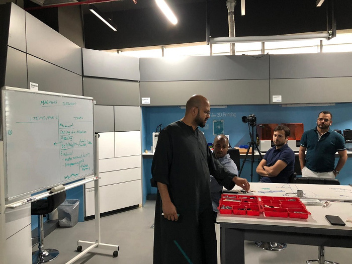
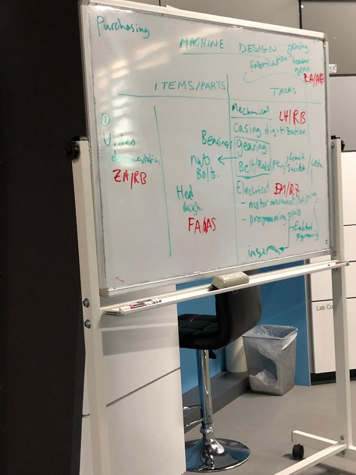
We started the process by planning how would the machine look like, and what needs to build, and assembled. Then we distributed the works that should be done among all team members according to their background and knowledge.
1. The mechanical design of the body (Luay and Ali)
2. The mechanical design of the head (Feras, and Ahmad)
3. The casing and packaging (Reeman and Zahir).
4. Electronics design and production (Rania and Einas).
Electronics Design and Production
Electronics design and production was the task assigned to me and to Einas to work on since we are both an ELectrical Engineers by background. Therefore after we had the meeting with the rest of the team and discussed the required need to be done inorder to design and fabricate this machine we immediately started with the process.
For simplicity and time limitation we decided to do a two axises design (x,y) so the machine will move in the x and y direction only. We started the process by testing the stepper motors we are going to use how they are going to work.
To control the stepper motor we used L293D Motor Driver IC and Arduino. As L293D IC has two H-Bridges, each H-Bridge will drive one of the electromagnetic coils of a stepper motor. By energizing these electromagnetic coils in a specific sequence, the shaft of a stepper can be moved forward or backward precisely in small steps.
The connections were the following:
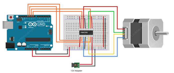
Start by connecting external 12V power supply to the Vcc2 pin and 5V output on Arduino to the Vcc1 pin. We also made sure that there were a common grounds in the circuit. Then we connected both the ENA & ENB pins to 5V output so the the motor is always enabled.
Also we connected the input pins(IN1, IN2, IN3 and IN4) of the L293D IC to four digital output pins(12, 11, 10 and 9) on Arduino. Finally, we connected the A+ (Red), A- (Blue), B+ (Green) and B- (Black) wires from the stepper motor to the L293D’s output pins (Out4, Out3, Out2 & Out1).
The arduino code to operate the stepper motor that we used is the following:
// Include the Arduino Stepper Library
#include <Stepper.h>

// Number of steps per output rotation
const int stepsPerRevolution = 200;

// Create Instance of Stepper library
Stepper myStepper(stepsPerRevolution, 12, 11, 10, 9);


void setup()
{
	// set the speed at 60 rpm:
	myStepper.setSpeed(60);
	// initialize the serial port:
	Serial.begin(9600);
}

void loop()
{
	// step one revolution in one direction:
	Serial.println("clockwise");
	myStepper.step(stepsPerRevolution);
	delay(500);

	// step one revolution in the other direction:
	Serial.println("counterclockwise");
	myStepper.step(-stepsPerRevolution);
	delay(500);
}
Since we are using a motor driver that is basically a chip, we decided to design a PCB for the motor driver. The PCB consist of two L293D chips with terminal blocks to connect the motors and the drivers to it.
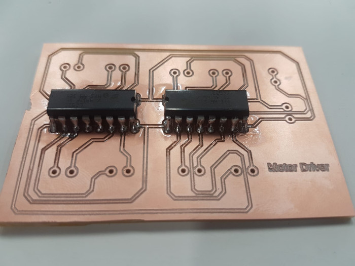
However, we did not do a fabduino for this assignment and intstead we used a commercial Arduino Uno to control the motor.
Finally the last thing to do was to understand and implement the application of G-code, so we can send it to the machine and fabricated. G-code is a programming language for CNC that instructs machines where and how to move. Most machines speak a different “dialect” of g-code, so the codes vary depending on type, make, and model. Each machine comes with an instruction manual that shows that particular machine’s code for a specific function.
For this task we used a software that creates a G-code which is Insckape.. Inkscape has no in built way of saving files as G-CODE. Therefore we had to install an Add-on that enables the export images to G-CODE files. This Add-on is the MakerBot Unicorn plugin..After we installed it, we open the Inkscape, then - File menu and click "Document Properties". First change dimensions from px to mm. Also reduce the width and height to 90 mm. Then close this window. A square appears as the drawing area. This is the area that we will use to write our text.
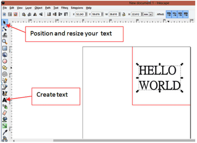
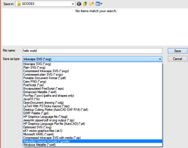
Finally, clicked on path and selected "object to path" the text is now ready to be saved as G-CODE. Clicked on file -> save as and then type the file name as "hello world" Change the file type to "MakerBot Unicon G-Code" as shown in below pic. This will only appear if the Add-on installation was successful. Finally clicked on save and click ok on the pop-up window.
After finishing with creating the G-code, we need the processor that would run the G-code. this processor called Processing IDE. After downloading the processing IDE, we downloaded the following code and opened it in the Processing IDE, and then clicked run. A window appeared with all the instructions. First we pressed p on the keyboard. The system asked to choose a port. So we selected the port on which your Arduino board is connected. Which in our case was port 6. Then we pressed g and browse to the folder where we saved our G-CODE. Select the right G-CODE and press enter. If everything was connected right, a device will start to plot on the paper. To terminate the process, just press x and the device will stop whatever it was doing.
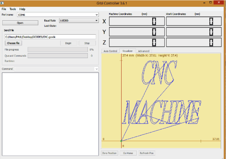
Once we’ve managed to generate a G-Code using Inkscape, it is necessary to view the G-Code in order to ensure that it is within the drawing limits. The drawing limits can be found in the arduino code below:
/*
 Send GCODE to this Sketch using gctrl.pde https://github.com/damellis/gctrl
 Convert SVG to GCODE with MakerBot Unicorn plugin for Inkscape available here https://github.com/martymcguire/inkscape-unicorn
 Arduino code for this Mini CNC Plotter based on: https://github.com/adidax/mini_cnc_plotter_firmware
*/

#include
#include

#define LINE_BUFFER_LENGTH 512

char STEP = MICROSTEP ;

// Servo position for Up and Down
const int penZUp = 115;
const int penZDown = 83;

// Servo on PWM pin 10
const int penServoPin =10 ;

// Should be right for DVD steppers, but is not too important here
const int stepsPerRevolution = 48;

// create servo object to control a servo
Servo penServo;

// Initialize steppers for X- and Y-axis using this Arduino pins for the L293D H-bridge
AF_Stepper myStepperY(stepsPerRevolution,1);
AF_Stepper myStepperX(stepsPerRevolution,2);

/* Structures, global variables    */
struct point {
  float x;
  float y;
  float z;
};

// Current position of plothead
struct point actuatorPos;

//  Drawing settings, should be OK
float StepInc = 1;
int StepDelay = 0;
int LineDelay =0;
int penDelay = 50;

// Motor steps to go 1 millimeter.
// Use test sketch to go 100 steps. Measure the length of line.
// Calculate steps per mm. Enter here.
float StepsPerMillimeterX = 100.0;
float StepsPerMillimeterY = 100.0;

// Drawing robot limits, in mm
// OK to start with. Could go up to 50 mm if calibrated well.
float Xmin = 0;
float Xmax = 40;
float Ymin = 0;
float Ymax = 40;
float Zmin = 0;
float Zmax = 1;

float Xpos = Xmin;
float Ypos = Ymin;
float Zpos = Zmax;

// Set to true to get debug output.
boolean verbose = false;

//  Needs to interpret
//  G1 for moving
//  G4 P300 (wait 150ms)
//  M300 S30 (pen down)
//  M300 S50 (pen up)
//  Discard anything with a (
//  Discard any other command!

/**********************
 * void setup() - Initialisations
 ***********************/
void setup() {
  //  Setup

  Serial.begin( 9600 );

  penServo.attach(penServoPin);
  penServo.write(penZUp);
  delay(100);

  // Decrease if necessary
  myStepperX.setSpeed(600);
  myStepperY.setSpeed(600);

  //  Set & move to initial default position
  // TBD

  //  Notifications!!!
  Serial.println("Mini CNC Plotter alive and kicking!");
  Serial.print("X range is from ");
  Serial.print(Xmin);
  Serial.print(" to ");
  Serial.print(Xmax);
  Serial.println(" mm.");
  Serial.print("Y range is from ");
  Serial.print(Ymin);
  Serial.print(" to ");
  Serial.print(Ymax);
  Serial.println(" mm.");
}

/**********************
 * void loop() - Main loop
 ***********************/
void loop()
{

  delay(100);
  char line[ LINE_BUFFER_LENGTH ];
  char c;
  int lineIndex;
  bool lineIsComment, lineSemiColon;

  lineIndex = 0;
  lineSemiColon = false;
  lineIsComment = false;

  while (1) {

    // Serial reception - Mostly from Grbl, added semicolon support
    while ( Serial.available()>0 ) {
      c = Serial.read();
      if (( c == '\n') || (c == '\r') ) {             // End of line reached
        if ( lineIndex > 0 ) {                        // Line is complete. Then execute!
          line[ lineIndex ] = '\0';                   // Terminate string
          if (verbose) {
            Serial.print( "Received : ");
            Serial.println( line );
          }
          processIncomingLine( line, lineIndex );
          lineIndex = 0;
        }
        else {
          // Empty or comment line. Skip block.
        }
        lineIsComment = false;
        lineSemiColon = false;
        Serial.println("ok");
      }
      else {
        if ( (lineIsComment) || (lineSemiColon) ) {   // Throw away all comment characters
          if ( c == ')' )  lineIsComment = false;     // End of comment. Resume line.
        }
        else {
          if ( c <= ' ' ) {                           // Throw away whitepace and control characters
          }
          else if ( c == '/' ) {                    // Block delete not supported. Ignore character.
          }
          else if ( c == '(' ) {                    // Enable comments flag and ignore all characters until ')' or EOL.
            lineIsComment = true;
          }
          else if ( c == ';' ) {
            lineSemiColon = true;
          }
          else if ( lineIndex >= LINE_BUFFER_LENGTH-1 ) {
            Serial.println( "ERROR - lineBuffer overflow" );
            lineIsComment = false;
            lineSemiColon = false;
          }
          else if ( c >= 'a' && c <= 'z' ) {        // Upcase lowercase
            line[ lineIndex++ ] = c-'a'+'A';
          }
          else {
            line[ lineIndex++ ] = c;
          }
        }
      }
    }
  }
}

void processIncomingLine( char* line, int charNB ) {
  int currentIndex = 0;
  char buffer[ 64 ];                                 // Hope that 64 is enough for 1 parameter
  struct point newPos;

  newPos.x = 0.0;
  newPos.y = 0.0;

  //  Needs to interpret
  //  G1 for moving
  //  G4 P300 (wait 150ms)
  //  G1 X60 Y30
  //  G1 X30 Y50
  //  M300 S30 (pen down)
  //  M300 S50 (pen up)
  //  Discard anything with a (
  //  Discard any other command!

  while( currentIndex < charNB ) {
    switch ( line[ currentIndex++ ] ) {              // Select command, if any
    case 'U':
      penUp();
      break;
    case 'D':
      penDown();
      break;
    case 'G':
      buffer[0] = line[ currentIndex++ ];          // /!\ Dirty - Only works with 2 digit commands
      //      buffer[1] = line[ currentIndex++ ];
      //      buffer[2] = '\0';
      buffer[1] = '\0';

      switch ( atoi( buffer ) ){                   // Select G command
      case 0:                                   // G00 & G01 - Movement or fast movement. Same here
      case 1:
        // /!\ Dirty - Suppose that X is before Y
        char* indexX = strchr( line+currentIndex, 'X' );  // Get X/Y position in the string (if any)
        char* indexY = strchr( line+currentIndex, 'Y' );
        if ( indexY <= 0 ) {
          newPos.x = atof( indexX + 1);
          newPos.y = actuatorPos.y;
        }
        else if ( indexX <= 0 ) {
          newPos.y = atof( indexY + 1);
          newPos.x = actuatorPos.x;
        }
        else {
          newPos.y = atof( indexY + 1);
          indexY = '\0';
          newPos.x = atof( indexX + 1);
        }
        drawLine(newPos.x, newPos.y );
        //        Serial.println("ok");
        actuatorPos.x = newPos.x;
        actuatorPos.y = newPos.y;
        break;
      }
      break;
    case 'M':
      buffer[0] = line[ currentIndex++ ];        // /!\ Dirty - Only works with 3 digit commands
      buffer[1] = line[ currentIndex++ ];
      buffer[2] = line[ currentIndex++ ];
      buffer[3] = '\0';
      switch ( atoi( buffer ) ){
      case 300:
        {
          char* indexS = strchr( line+currentIndex, 'S' );
          float Spos = atof( indexS + 1);
          //         Serial.println("ok");
          if (Spos == 30) {
            penDown();
          }
          if (Spos == 50) {
            penUp();
          }
          break;
        }
      case 114:                                // M114 - Repport position
        Serial.print( "Absolute position : X = " );
        Serial.print( actuatorPos.x );
        Serial.print( "  -  Y = " );
        Serial.println( actuatorPos.y );
        break;
      default:
        Serial.print( "Command not recognized : M");
        Serial.println( buffer );
      }
    }
  }
}

/*********************************
 * Draw a line from (x0;y0) to (x1;y1).
 * int (x1;y1) : Starting coordinates
 * int (x2;y2) : Ending coordinates
 **********************************/
void drawLine(float x1, float y1) {

  if (verbose)
  {
    Serial.print("fx1, fy1: ");
    Serial.print(x1);
    Serial.print(",");
    Serial.print(y1);
    Serial.println("");
  }

  //  Bring instructions within limits
  if (x1 >= Xmax) {
    x1 = Xmax;
  }
  if (x1 <= Xmin) {
    x1 = Xmin;
  }
  if (y1 >= Ymax) {
    y1 = Ymax;
  }
  if (y1 <= Ymin) {
    y1 = Ymin;
  }

  if (verbose)
  {
    Serial.print("Xpos, Ypos: ");
    Serial.print(Xpos);
    Serial.print(",");
    Serial.print(Ypos);
    Serial.println("");
  }

  if (verbose)
  {
    Serial.print("x1, y1: ");
    Serial.print(x1);
    Serial.print(",");
    Serial.print(y1);
    Serial.println("");
  }

  //  Convert coordinates to steps
  x1 = (int)(x1*StepsPerMillimeterX);
  y1 = (int)(y1*StepsPerMillimeterY);
  float x0 = Xpos;
  float y0 = Ypos;

  //  Let's find out the change for the coordinates
  long dx = abs(x1-x0);
  long dy = abs(y1-y0);
  int sx = x0 dy) {
    for (i=0; i=dx) {
        over-=dx;
        myStepperY.onestep(sy,STEP);
      }
    delay(StepDelay);
    }
  }
  else {
    for (i=0; i=dy) {
        over-=dy;
        myStepperX.onestep(sx,STEP);
      }
      delay(StepDelay);
    }
  }

  if (verbose)
  {
    Serial.print("dx, dy:");
    Serial.print(dx);
    Serial.print(",");
    Serial.print(dy);
    Serial.println("");
  }

  if (verbose)
  {
    Serial.print("Going to (");
    Serial.print(x0);
    Serial.print(",");
    Serial.print(y0);
    Serial.println(")");
  }

  //  Delay before any next lines are submitted
  delay(LineDelay);
  //  Update the positions
  Xpos = x1;
  Ypos = y1;
}

//  Raises pen
void penUp() {
  penServo.write(penZUp);
  delay(penDelay);
  Zpos=Zmax;
  digitalWrite(15, LOW);
    digitalWrite(16, HIGH);
  if (verbose) {
    Serial.println("Pen up!");

  }
}
//  Lowers pen
void penDown() {
  penServo.write(penZDown);
  delay(penDelay);
  Zpos=Zmin;
  digitalWrite(15, HIGH);
    digitalWrite(16, LOW);
  if (verbose) {
    Serial.println("Pen down.");
  }
}
To be able to understand how to create the G-code we followed this tutorial steps by steps, and we took few files from them to be able to operate our machines.
Machine Designing
Rest of the teams did there parts as well, and you can check their website to follow the rest of the process.
1. The mechanical design of the body (Ali and Luay)
2. The mechanical design of the head (Feras, and Ahmad)
3. The casing and packaging (Reeman and Zahir).
And you can find the video of the Machine Desiging week here: